Hydraulics and Mathematical Formulas in Civil Engineering
Abstract: Hydraulics is a fundamental branch of civil engineering that encompasses the study of fluid behavior and the design of hydraulic systems. It plays a crucial role in various applications such as water supply, wastewater management, drainage systems, and hydraulic structures. Mathematical formulas are essential tools in hydraulics, enabling engineers to analyze and design these systems accurately. These formulas allow for the calculation of critical parameters like flow rates, pressure drops, and velocities. Key formulas include the Bernoulli equation, Darcy-Weisbach equation, Manning’s equation, and others related to flow measurement, pipe flow, and hydraulic structures. Understanding hydraulics and mathematical formulas is vital for civil engineers to make informed decisions during the design process, optimizing system performance and ensuring the efficient management of water resources. By applying mathematical principles, engineers can tackle complex challenges and develop sustainable solutions for hydraulic engineering projects.

INTRODUCTION
Hydraulics is a fundamental branch of civil engineering that deals with the behavior and applications of fluids, particularly water, in engineering systems. It encompasses the study of fluid properties, fluid flow, and the design of hydraulic structures and systems. In the field of civil engineering, hydraulics plays a crucial role in water supply and distribution, wastewater management, drainage systems, irrigation, and hydraulic structures such as dams, canals, and pipelines.
Mathematical formulas are essential tools in hydraulics, providing engineers with the means to analyze and design hydraulic systems. These formulas allow for the calculation of flow rates, pressure drops, velocities, and other parameters critical to understanding fluid behavior and optimizing system performance. By utilizing mathematical formulas, engineers can accurately predict and model fluid flow, ensuring the efficiency, safety, and reliability of hydraulic engineering projects.
Key mathematical formulas commonly used in hydraulics include the Bernoulli equation, Darcy-Weisbach equation, Manning’s equation, continuity equation, and various formulas related to flow measurement, pipe flow, open channel flow, and hydraulic structures. These formulas provide valuable insights into fluid behavior, enable the determination of system characteristics, and guide the design process.
A thorough understanding of hydraulics and the associated mathematical formulas is essential for civil engineers to effectively analyze and design hydraulic systems. It enables them to make informed decisions regarding the selection of pipe sizes, pump capacities, flow control devices, and hydraulic structures. By applying mathematical principles to hydraulic engineering problems, engineers can optimize system performance, minimize energy losses, and ensure the sustainable and reliable management of water resources.
In summary, hydraulics is a vital field of study in civil engineering, focusing on the behavior of fluids in engineering systems. Mathematical formulas serve as powerful tools in analyzing and designing hydraulic systems, providing engineers with the means to accurately predict fluid behavior and optimize system performance. With the knowledge of hydraulics and mathematical formulas, civil engineers can tackle complex hydraulic engineering challenges and develop efficient and sustainable solutions for various water-related projects.
Again, hydraulics is a fundamental branch of civil engineering that deals with the behavior of fluids, particularly water, and its interaction with structures. It involves the study of fluid flow, fluid properties, and the principles governing fluid behavior. Here are a few important hydraulic formulas commonly used in civil engineering:
- Continuity Equation: A₁V₁ = A₂V₂, where A represents cross-sectional area and V represents velocity. This equation ensures that the mass flow rate remains constant in an incompressible fluid within a closed system.
- Bernoulli’s Equation: P + ½ρV² + ρgh = constant, where P is pressure, ρ is density, V is velocity, g is acceleration due to gravity, and h is height. Bernoulli’s equation describes the conservation of energy in fluid flow and is useful for analyzing fluid flow along pipes, nozzles, and venturis.
- Darcy’s Law: Q = -KA(dh/dL), where Q is the flow rate, K is the hydraulic conductivity, A is the cross-sectional area, dh/dL is the hydraulic gradient, and – sign indicates flow direction. Darcy’s Law is used to determine the flow of water through porous media, such as soil, and helps in the design of drainage systems and filtration processes.
- Manning’s Equation: Q = (1/n)A(R^(2/3))(S^(1/2)), where Q is the flow rate, n is Manning’s roughness coefficient, A is the cross-sectional area, R is the hydraulic radius, and S is the slope of the energy grade line. Manning’s Equation is commonly employed to calculate the flow velocity and capacity of open channels, such as rivers, canals, and stormwater drains.
- Hazen-Williams Equation: Q = (C)(A)(R^(0.63))(S^(0.54)), where Q is the flow rate, C is the Hazen-Williams coefficient, A is the cross-sectional area, R is the hydraulic radius, and S is the slope. This formula is frequently used to estimate the flow of water through pipes, providing information for pipe sizing and water distribution system design.
These are just a few examples of hydraulic formulas used in civil engineering. Understanding and applying these equations is essential for hydraulic design, analysis of water systems, and ensuring the efficient and safe transport of fluids in civil engineering projects.
PROPERTIES OF FLUID
In civil engineering, understanding the properties of fluids, particularly water, is crucial for the design and analysis of various hydraulic systems. Here are some important properties of fluids that are relevant in civil engineering:
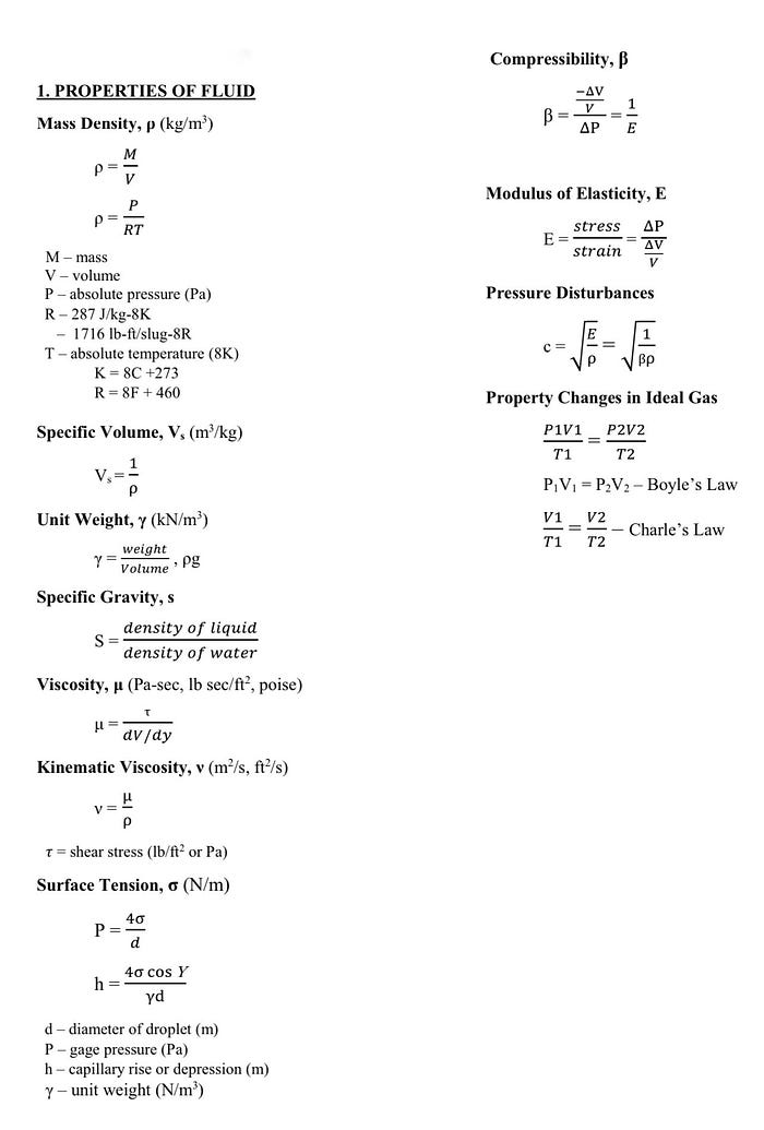
- Density: Density refers to the mass per unit volume of a fluid. It is denoted by the symbol ρ (rho) and is typically measured in kilograms per cubic meter (kg/m³). In hydraulic engineering, knowledge of fluid density is important for calculating forces exerted by flowing water on structures such as dams, weirs, and pipelines.
- Viscosity: Viscosity is a measure of a fluid’s resistance to flow or internal friction. It determines how easily a fluid can deform under an applied shear stress. High-viscosity fluids, such as thick oils, flow slowly, while low-viscosity fluids, like water, flow more readily. Viscosity is denoted by the symbol μ (mu) and is measured in units of pascal-seconds (Pa·s) or centipoise (cP). Understanding viscosity is crucial for analyzing fluid behavior in pipes, channels, and pumps.
- Surface Tension: Surface tension is the cohesive force between molecules at the surface of a liquid, which tends to minimize the surface area. It causes liquids to form droplets or exhibit capillary action. Surface tension is particularly important in civil engineering when considering water retention, soil moisture movement, and the behavior of liquids in porous media.
- Compressibility: Compressibility refers to a fluid’s ability to be compressed under the influence of pressure. In civil engineering, fluids are often assumed to be incompressible, which means their density remains nearly constant even under significant changes in pressure. Water is typically considered an incompressible fluid for most engineering applications, but for specific cases, such as deep-sea applications, the compressibility of water may become relevant.
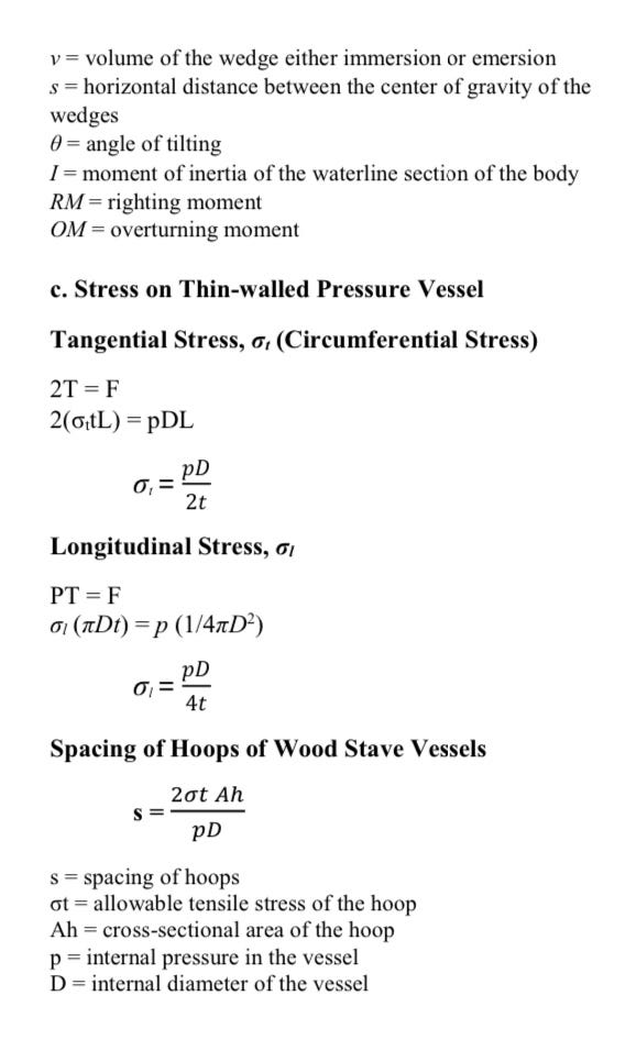
- Bulk Modulus: The bulk modulus of a fluid is a measure of its resistance to changes in volume under uniform pressure. It quantifies the fluid’s compressibility and is denoted by the symbol K. Bulk modulus plays a role in the analysis of fluid behavior under dynamic loads, such as water hammer effects in pipelines and the stability of hydraulic systems.
Understanding and accounting for these fluid properties is essential in various civil engineering applications, including water supply and distribution systems, drainage and sewer systems, hydraulic structures, and environmental engineering projects.
PRINCIPLES OF HYDROSTATICS
Hydrostatics is an essential aspect of civil engineering that deals with the behavior of fluids at rest. It involves the study of principles related to fluids, such as water, in static equilibrium under the influence of gravity. Here are some key principles of hydrostatics in civil engineering:
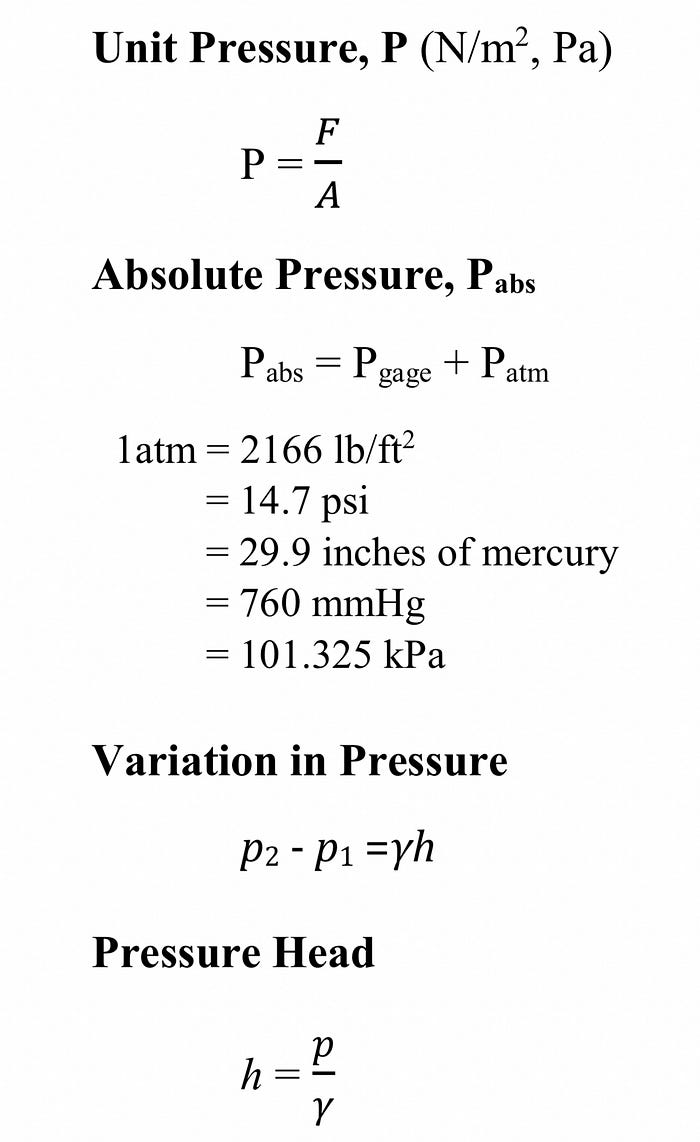
- Pascal’s Law: This principle states that any change in pressure applied to an enclosed fluid is transmitted undiminished to all portions of the fluid and the surrounding container. In civil engineering, Pascal’s law helps in understanding the behavior of fluid pressure in hydraulic systems and is vital for the design and analysis of structures like dams, pipelines, and water distribution networks.
- Pressure at a Point: The pressure exerted by a fluid at a particular point is equal in all directions. It increases with depth due to the weight of the fluid above. This principle is crucial when designing foundations for structures, such as tall buildings and bridges, to ensure they can withstand the pressure exerted by the surrounding soil and water.
- Hydrostatic Pressure: Hydrostatic pressure is the pressure exerted by a fluid at a given depth. It is directly proportional to the density of the fluid, acceleration due to gravity, and the depth of the fluid. Civil engineers consider hydrostatic pressure when designing structures such as retaining walls and swimming pools to ensure their stability and prevent any failure caused by excessive pressure.
- Buoyancy: The principle of buoyancy states that an object submerged in a fluid experiences an upward force equal to the weight of the fluid it displaces. In civil engineering, buoyancy is important when designing structures that are partially or fully submerged, like ships, offshore platforms, and floating bridges. Engineers need to consider the buoyant forces to ensure the stability and safety of these structures.
- Archimedes’ Principle: Archimedes’ principle states that the buoyant force acting on a submerged or floating object is equal to the weight of the fluid it displaces. This principle helps engineers understand the behavior of floating structures, stability of dams and reservoirs, and the design of buoyancy control systems.
Understanding the principles of hydrostatics is crucial in civil engineering as it helps engineers analyze and design structures that interact with fluids, ensuring their stability, safety, and performance under different hydrostatic conditions.
TOTAL HYDROSTATIC FORCE
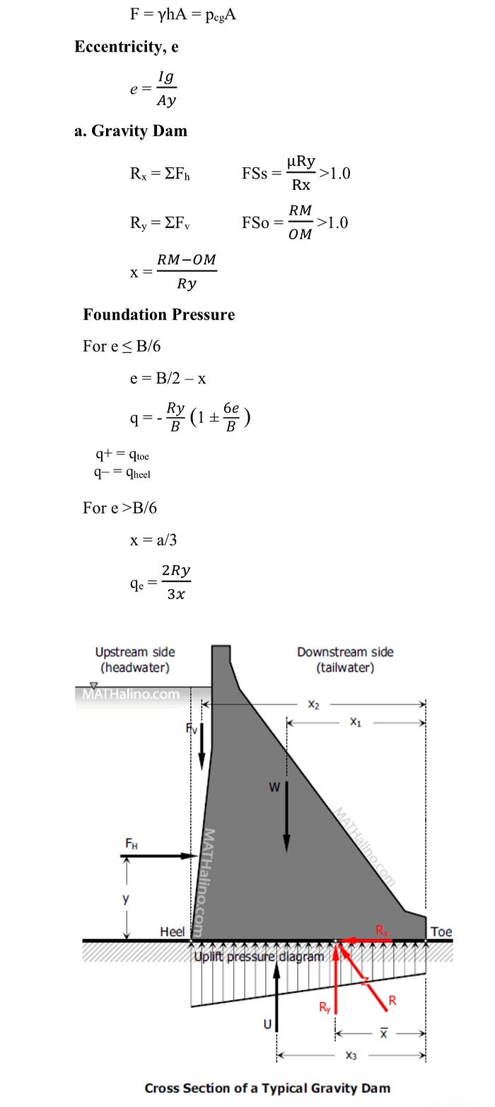
Total hydrostatic force is a concept in civil engineering that refers to the cumulative force exerted by a fluid, typically water, on a submerged or partially submerged surface. It is an important consideration when designing structures that interact with water bodies, such as dams, retaining walls, and submerged foundations.
The total hydrostatic force acting on a surface depends on several factors, including the density of the fluid, the depth of the fluid above the surface, and the shape and orientation of the surface. The force is primarily a result of the pressure distribution across the surface due to the weight of the fluid.
The magnitude of the total hydrostatic force can be calculated using the principles of hydrostatics. The force is typically calculated as the product of the pressure at a particular depth and the area of the surface that is exposed to the fluid. By integrating the pressure over the entire surface, the total force can be determined.
For example, in the design of a retaining wall, engineers need to consider the total hydrostatic force exerted by the soil and groundwater against the wall. This force helps determine the stability and design parameters of the wall, such as its thickness, reinforcement requirements, and anchoring systems.
Similarly, in the design of dams, the total hydrostatic force acting on the dam structure is a critical factor. The force exerted by the water on the dam determines its stability and the capacity of the structure to resist the force. Engineers analyze the distribution of forces on the dam and design appropriate structures to withstand the pressure and prevent any failure or deformation.

Understanding the total hydrostatic force is essential in civil engineering as it ensures the structural integrity and safety of various water-related structures. By accurately assessing and accounting for the hydrostatic forces, engineers can design structures that can withstand the pressures exerted by water bodies, ensuring their long-term performance and stability.
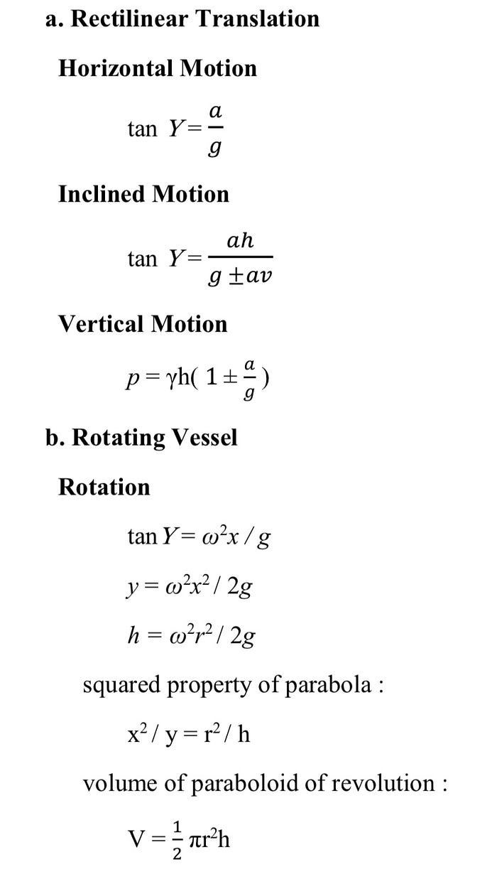
RELATIVE EQUILIBRIUM OF LIQUIDS
In civil engineering, the concept of relative equilibrium of liquids refers to the stable condition in which multiple liquids of different densities coexist without mixing due to the force of gravity. This phenomenon is also known as stratification or layering.
When liquids with different densities are placed in a container, they tend to settle into distinct layers according to their density. The denser liquid settles at the bottom, while the lighter liquid occupies the upper layer. This separation occurs because of the variation in hydrostatic pressures at different depths within the liquid column.
The principle of relative equilibrium of liquids is often encountered in the design and operation of various civil engineering structures involving fluids. Some examples include:
- Water treatment plants: In the treatment of water, different chemicals or substances may be added to the water for purification purposes. These substances can have different densities. The principle of relative equilibrium ensures that the added substances mix appropriately and settle in separate layers for effective treatment processes.
2. Sedimentation tanks: Sedimentation tanks are commonly used in wastewater treatment systems. They allow the separation of solid particles from liquid by the force of gravity. The principle of relative equilibrium ensures that the settled solids are effectively separated from the liquid, allowing for the removal and further treatment of the sediment.
3. Reservoirs and dams: Large bodies of water, such as reservoirs formed by dams, can have stratification due to variations in temperature and dissolved substances. This stratification affects water quality and the distribution of dissolved oxygen. Understanding the relative equilibrium of liquids helps engineers manage and maintain the water quality in such reservoirs for various purposes, including drinking water supply, aquatic ecosystems, and power generation.
4. Storage tanks: Storage tanks used in various industries often contain liquids with different densities. The principle of relative equilibrium helps in ensuring that the liquids remain stratified, preventing unwanted mixing and maintaining the desired composition of the stored substances.
By considering the principle of relative equilibrium of liquids, civil engineers can effectively design and operate structures and systems involving fluids. Understanding the behavior of stratified liquids helps ensure the efficient and safe operation of water treatment processes, sedimentation systems, reservoir management, and storage facilities.
FUNDAMENTALS OF FLUID FLOW
Fluid flow is a fundamental aspect of civil engineering, involving the study of how fluids, such as water or air, move and interact with structures and the environment. Understanding the fundamentals of fluid flow is essential for the design and analysis of various civil engineering systems and structures. Here are some key concepts related to fluid flow:

- Continuity Equation: The continuity equation states that the mass flow rate of a fluid remains constant along a streamline. It emphasizes that the flow of a fluid must be conserved, meaning that the amount of fluid entering a system must be equal to the amount leaving. The continuity equation is crucial in analyzing pipe networks, open channel flows, and other fluid conveyance systems.
- Bernoulli’s Principle: Bernoulli’s principle describes the relationship between fluid pressure, velocity, and elevation. It states that in a streamline flow of an inviscid and incompressible fluid, the sum of the pressure, kinetic energy per unit volume, and potential energy per unit volume remains constant. This principle is valuable in analyzing fluid flow in pipes, open channels, and around objects, aiding in the design of structures such as pumps, turbines, and aircraft wings.
- Reynolds Number: The Reynolds number is a dimensionless quantity used to determine the flow regime of a fluid. It relates the fluid’s density, velocity, and viscosity to its characteristic length. Understanding the Reynolds number helps in identifying whether a flow is laminar (smooth and orderly) or turbulent (chaotic and irregular). This knowledge is crucial for designing pipes, channels, and other hydraulic structures to optimize flow characteristics and minimize energy losses.
- Darcy-Weisbach Equation: The Darcy-Weisbach equation is widely used in civil engineering to calculate head loss (pressure drop) in pipes and conduits due to friction. It relates the head loss to the fluid velocity, pipe characteristics, and friction factor. The equation assists engineers in determining pipe sizes, selecting pump capacities, and designing efficient fluid transport systems.
- Open Channel Flow: Open channel flow refers to the flow of a fluid in a channel with a free surface exposed to the atmosphere. It occurs in natural channels like rivers and man-made channels such as canals and stormwater drainage systems. Understanding open channel flow involves principles like Manning’s equation, which relates flow rate, channel geometry, and roughness, enabling engineers to predict water levels, velocities, and design channel dimensions.
By grasping these fundamentals of fluid flow, civil engineers can accurately analyze and design systems involving fluid transportation, drainage, and hydraulic structures. Whether it is optimizing water supply networks, mitigating flood risks, or designing efficient pipe systems, a solid understanding of fluid flow principles is essential for successful civil engineering projects.
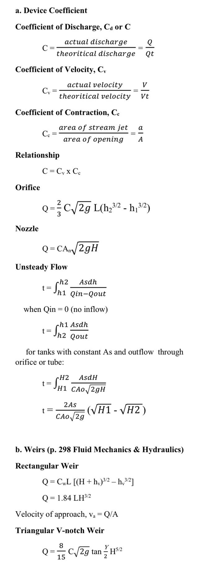
FLUID FLOW MEASUREMENT
Fluid flow measurement is a crucial aspect of civil engineering, as it allows engineers to accurately quantify and monitor the movement of fluids in various systems and structures. Precise flow measurement helps in designing efficient hydraulic systems, optimizing water management, and ensuring the performance and safety of fluid-related infrastructure. Here are some common methods and devices used for fluid flow measurement in civil engineering:
- Flowmeters: Flowmeters are devices specifically designed to measure the flow rate of fluids. Different types of flowmeters are available, including:
- Differential Pressure (DP) Flowmeters: These measure flow by creating a pressure difference across a constriction in the pipe or channel. Examples include orifice plates, venturi meters, and flow nozzles.
- Electromagnetic Flowmeters: These utilize Faraday’s law of electromagnetic induction to measure the flow rate of conductive fluids. Electromagnetic flowmeters are suitable for measuring flow in pipes and channels.
- Ultrasonic Flowmeters: These use ultrasonic waves to measure the velocity of the fluid and calculate the flow rate. They are non-intrusive and suitable for a wide range of applications.
- Turbine Flowmeters: These measure flow by the rotation of a turbine placed in the fluid stream. The rotation speed is directly proportional to the flow rate.
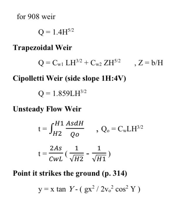
2. Weirs and Flumes: Weirs and flumes are hydraulic structures designed to measure flow in open channels. They create specific flow conditions that can be correlated to the flow rate. Common types include rectangular weirs, V-notch weirs, and Parshall flumes.
3. Current Meters: Current meters are used to measure the velocity of flowing water in rivers, canals, and other open channels. They typically consist of impellers or propellers that rotate when exposed to the flowing water. The rotation speed is correlated to the velocity.
4. Water Level Gauges: Water level gauges, such as staff gauges or pressure transducers, are used to measure the water level in tanks, reservoirs, and open channels. By recording the water level over time, the flow rate can be determined.
5. Data Loggers and Telemetry Systems: Data loggers and telemetry systems are used to collect, store, and transmit flow data from various measurement devices. They enable real-time monitoring, remote data retrieval, and analysis of flow patterns and trends.
Fluid flow measurement plays a vital role in the design, operation, and maintenance of water supply systems, wastewater treatment plants, irrigation systems, and stormwater management. Accurate flow measurements assist in assessing system performance, detecting leaks or blockages, optimizing resource allocation, and ensuring compliance with regulations. Civil engineers rely on reliable flow measurement techniques and devices to make informed decisions regarding fluid management and infrastructure planning.
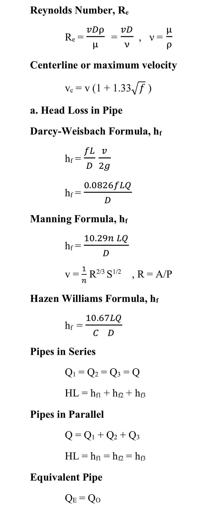
FLUID FLOW IN PIPES
Fluid flow in pipes is a fundamental aspect of civil engineering, as pipes are widely used for the conveyance of fluids in various applications, including water supply systems, wastewater networks, irrigation systems, and industrial processes. Understanding the principles of fluid flow in pipes is crucial for designing efficient and reliable pipe systems. Here are some key aspects related to fluid flow in pipes:
- Pipe Flow Regimes: Fluid flow in pipes can occur in different regimes, characterized by the flow behavior. Laminar flow refers to smooth and orderly flow with well-defined streamlines. Turbulent flow is characterized by chaotic and irregular motion, resulting in mixing and increased friction. The transition from laminar to turbulent flow depends on factors such as fluid velocity, pipe roughness, and pipe diameter.
- Pressure and Velocity Distribution: In pipe flow, pressure and velocity are not constant throughout the cross-section. The pressure decreases along the flow direction due to frictional losses, while the velocity profile is typically parabolic for laminar flow and flattened for turbulent flow. Understanding pressure and velocity distribution helps in analyzing flow characteristics and designing pipe systems to meet specific requirements.
- Reynolds Number: The Reynolds number is a dimensionless parameter that relates fluid density, velocity, and viscosity to the pipe’s diameter. It helps determine the flow regime in a pipe, whether it is laminar or turbulent. Engineers use the Reynolds number to assess the pipe’s performance, select appropriate pipe sizes, and predict the occurrence of turbulence.
- Frictional Losses: Frictional losses occur in pipe flow due to the interaction between the fluid and the pipe walls. These losses lead to a reduction in pressure along the pipe’s length. The Darcy-Weisbach equation and the Hazen-Williams equation are commonly used to calculate frictional losses and determine the pressure drop in pipe systems. Proper consideration of frictional losses is essential for efficient pipe design and sizing, pump selection, and energy optimization.
- Pipe Network Analysis: Civil engineers often deal with complex pipe networks, such as water distribution systems or sewer networks. Analyzing the flow behavior and performance of these networks involves applying principles of fluid flow in pipes, including the conservation of mass and energy. Techniques like Hardy-Cross method and EPANET software are used to simulate and optimize the flow distribution within pipe networks.
- Pipe Materials and Roughness: The choice of pipe materials and the level of pipe roughness significantly influence fluid flow in pipes. Different materials, such as PVC, ductile iron, or steel, have varying roughness characteristics, which affect frictional losses and flow capacity. Proper selection of pipe materials and consideration of roughness factors are important in achieving desired flow characteristics and minimizing energy losses.
Fluid flow in pipes is a critical aspect of many civil engineering projects. By understanding the principles of fluid flow, engineers can design efficient and reliable pipe systems that meet hydraulic requirements, optimize energy usage, and ensure the safe conveyance of fluids.
OPEN CHANNEL
In civil engineering, an open channel refers to a conduit or waterway through which a fluid, typically water, flows freely with a free surface exposed to the atmosphere. Open channels can be natural, such as rivers and streams, or man-made, such as canals, ditches, and stormwater drainage systems. Open channel flow is governed by specific principles and considerations that are essential in hydraulic engineering. Here are some key aspects related to open channels in civil engineering:
- Flow Characteristics: Open channel flow can be classified into different flow regimes based on the relationship between the flow depth and the channel’s hydraulic properties. The common flow classifications include uniform flow, gradually varied flow, and rapidly varied flow. Understanding these flow characteristics is crucial for designing and analyzing open channel systems.
- Manning’s Equation: Manning’s equation is widely used in open channel flow to calculate flow velocity, flow rate, or channel slope. It relates these parameters to the hydraulic radius, cross-sectional shape, and Manning’s roughness coefficient. This equation is a valuable tool in designing open channels and determining their capacity and performance.
- Channel Geometry: The geometry of an open channel, including its cross-sectional shape, width, and slope, plays a significant role in determining the flow characteristics. Engineers need to consider these parameters to ensure efficient flow, prevent excessive erosion or sedimentation, and optimize the hydraulic performance of the channel.
- Hydraulic Structures: Open channels often incorporate hydraulic structures to control the flow, manage water levels, or regulate the discharge. These structures can include weirs, gates, culverts, drop structures, and diversion channels. Proper design and placement of these structures are essential for effective water management, flood control, and water distribution.
- Sediment Transport: Open channels are prone to sediment transport, where solid particles are carried by the flowing water. Understanding sediment transport is crucial in designing channels to prevent sedimentation and erosion issues. Proper sediment management techniques, such as erosion control measures and sediment basins, are employed to maintain the long-term performance of open channels.
- Flood Control and Drainage: Open channels play a vital role in flood control and drainage systems. They help convey excess water from heavy rainfall events, preventing flooding and minimizing damage to surrounding areas. Proper channel sizing, alignment, and maintenance are essential to ensure effective drainage and flood management.
Civil engineers extensively study open channels to design and manage various water-related infrastructure projects. This includes irrigation systems, stormwater management, drainage networks, wastewater treatment plants, and water supply systems. Accurate analysis and design of open channels are crucial to ensure efficient water conveyance, prevent erosion, manage sedimentation, and promote the sustainable use of water resources.
CONCLUSION
In conclusion, hydraulics is an indispensable discipline within civil engineering that addresses the behavior and practical applications of fluids, particularly water, in engineering systems. The study of hydraulics enables engineers to understand fluid properties, fluid flow dynamics, and the design of hydraulic structures critical to water supply, wastewater management, drainage systems, irrigation, and more.
Mathematical formulas play a vital role in hydraulics, empowering engineers to analyze and design hydraulic systems with precision. By utilizing these formulas, engineers can calculate essential parameters such as flow rates, pressure drops, velocities, and more, thereby gaining valuable insights into fluid behavior and optimizing the performance of hydraulic engineering projects. The Bernoulli equation, Darcy-Weisbach equation, Manning’s equation, continuity equation, and various other formulas related to flow measurement, pipe flow, open channel flow, and hydraulic structures are essential tools in the hydraulics toolkit.
A comprehensive understanding of hydraulics and its associated mathematical formulas is paramount for civil engineers to effectively analyze and design hydraulic systems. This knowledge empowers engineers to make informed decisions when selecting pipe sizes, pump capacities, flow control devices, and hydraulic structures, ensuring optimal system performance. By applying mathematical principles to hydraulic engineering problems, engineers can minimize energy losses, optimize system efficiency, and promote the sustainable and reliable management of water resources.
In summary, hydraulics is a cornerstone discipline in civil engineering, focusing on the behavior of fluids in engineering systems. The application of mathematical formulas within hydraulics provides engineers with the necessary tools to predict fluid behavior accurately and design hydraulic systems that meet the demands of various water-related projects. With a firm grasp of hydraulics and mathematical formulas, civil engineers can tackle intricate hydraulic engineering challenges and develop efficient, sustainable solutions that contribute to the effective management of our water resources.